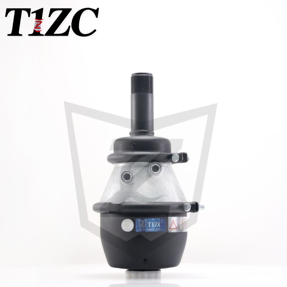
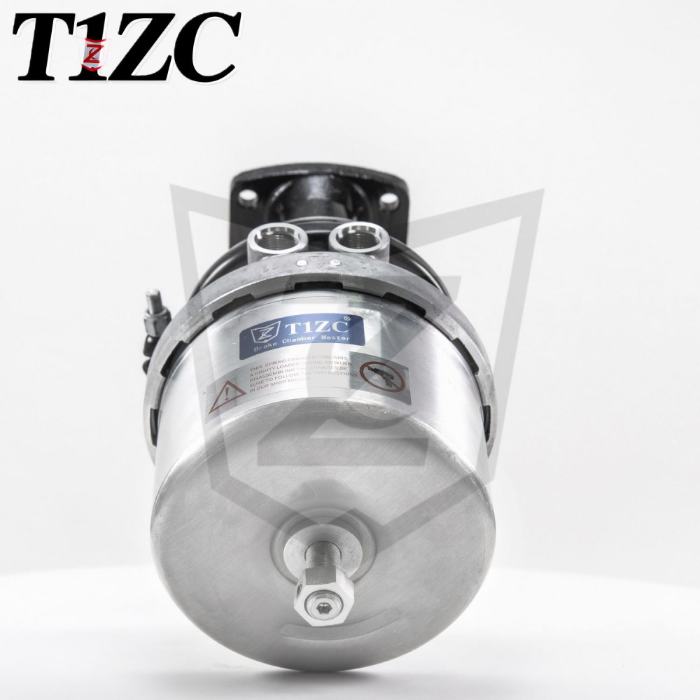
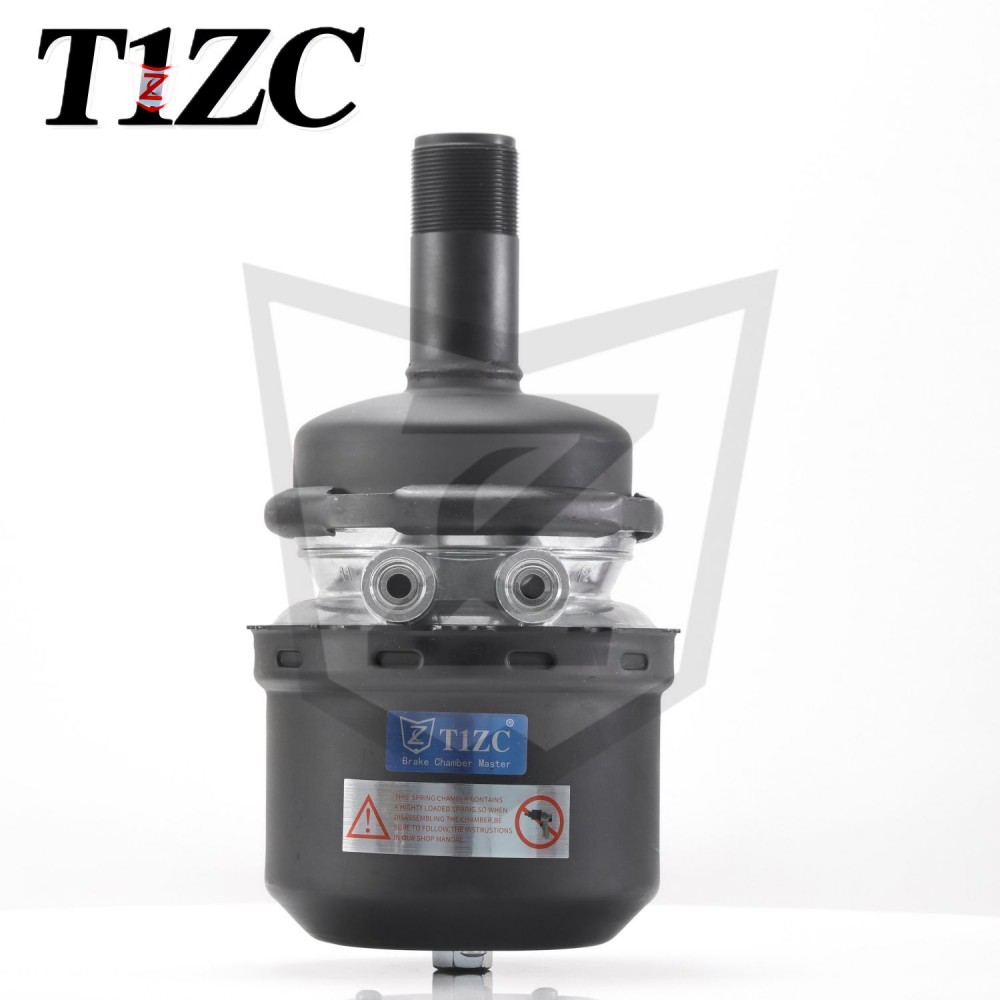
Brake chamber: the core executor and safety guardian of the pneumatic brake system of commercial vehicles
1. Concept definition: the hub of power conversion
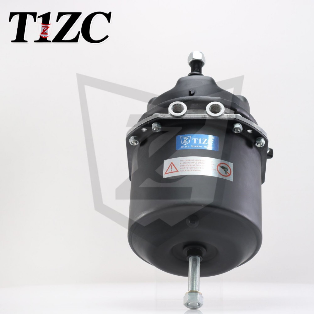
Brake chamber, also known as brake cylinder (different from the cylinder of hydraulic brake system), is a crucial actuator in the pneumatic brake system. It is installed near each wheel (usually on the brake of the axle), playing the core role of "energy converter" and "action executor". Its core task is to efficiently and reliably convert the compressed air pressure energy output from the brake master valve or relay valve into mechanical push rod force (or rotational motion), and then push the camshaft, S-cam or wedge mechanism of the brake system, and finally prompt the brake shoe (friction plate) to press the brake drum (or brake disc), generate a strong friction torque, and achieve vehicle deceleration or parking.
In short: compressed air → brake chamber → mechanical thrust → braking action. It is the last link in the pneumatic brake command chain, which is directly related to the size and response speed of the braking force.
2. In-depth analysis: working principle, structure and key details
Core working principle (taking the most common diaphragm type as an example):
Standby brake: When the driver does not step on the brake pedal, the inside of the brake chamber is connected to the atmosphere and there is no air pressure. The internal return spring (return spring) makes the push rod fully retracted and the brake is in the released position.
Braking process:
The driver steps on the brake pedal and compressed air is output from the main brake valve.
The compressed air enters the brake chamber through the pipeline and acts on one side of the rubber diaphragm (or piston).
The air pressure overcomes the elastic force of the return spring and pushes the diaphragm (or piston) to the other side.
The movement of the diaphragm (or piston) drives the push rod connected to it to extend outward.
The extended push rod acts on the brake's adjustment arm, driving the camshaft (or S cam, wedge) to rotate or move.
The movement of the cam pushes the brake shoe outward, making it in close contact with the inner wall of the brake drum (or brake disc), generating braking force.
Release the brake: When the driver releases the pedal, the main brake valve cuts off the air supply and discharges the compressed air in the brake chamber into the atmosphere. The elastic force of the return spring quickly pulls the push rod back to its original position, and at the same time drives the brake cam to rotate. The brake shoe is separated from the brake drum/disc under the action of the return spring, and the brake is released.
Core structure and components:
Housing: Usually made of high-strength aluminum alloy or stamped steel, divided into two parts, the front cover and the rear cover, forming a sealed chamber.
Diaphragm/piston:
Diaphragm type: Use a large area, oil-resistant and heat-resistant rubber diaphragm as a pressure-acting element. It has a relatively simple structure, low cost, and fast response (initial stroke), and is the most widely used type. However, there are restrictions on the push rod stroke, and the diaphragm may fatigue and age after long-term use.
Piston type: Use a metal piston (usually with a sealing ring) instead of a diaphragm. More durable, can withstand higher pressure, allow a larger push rod stroke, usually better sealing, and a long maintenance cycle. Commonly used in heavy vehicles or applications that require long strokes (such as disc brakes). The cost is relatively high.
Push rod: A solid metal rod with one end connected to the diaphragm/piston and the other end extending out of the housing to connect to the brake's adjustment arm. Responsible for transmitting thrust.
Return spring: Located behind the diaphragm/piston (on the non-air pressure side), it provides a strong return force when the brake is released, ensuring that the push rod is quickly and completely retracted and the brake is completely released.
Air inlet: Connects to the compressed air line from the brake valve.
Exhaust port/breathing hole: Connects to the atmosphere in the non-braking state to ensure that air can flow in and out freely and avoid the formation of a vacuum that hinders the return. Modern air chambers often have built-in non-return valves or dust filters.
Clamp/bolt: Firmly seals and presses the front and rear housings together.
Key role: Spring brake cylinder (Spring Brake Chamber)
The spring brake cylinder is commonly used in the parking brake and emergency brake systems of modern heavy commercial vehicles. It integrates the conventional service brake air chamber (Service Chamber) and a powerful energy storage spring cylinder (Spring Brake) in one housing (usually arranged in series).
Working principle (the key lies in "spring energy storage release"):
Parking/emergency braking: When the vehicle needs to park or the service brake fails, the compressed air in the spring brake cylinder is released. At this time, the huge pre-compressed spring is released, and its elastic force pushes the second push rod (parking push rod) inside. This thrust is superimposed on the service brake push rod through mechanical linkage (usually between push rods), generating a strong braking force to lock the wheel. This is the "safe state" of the vehicle-no air brake.
Driving preparation state: When the vehicle starts, compressed air is filled into the spring brake cylinder, compressing the energy storage spring, releasing its force on the push rod, and the service brake air chamber resumes normal operation. Sufficient air pressure must be established (usually marked with a release air pressure scale) before the spring force can be completely overcome and the parking brake can be released.
Importance: Provides highly reliable parking and emergency braking force independent of the service brake system. Even if the entire vehicle is out of air (such as engine shutdown, serious pipeline leakage), the strong spring force can automatically apply braking, which is the last line of defense to ensure vehicle parking safety and deal with service brake failure.
Main types and features:
Standard brake chamber: only includes service brake function (diaphragm or piston).
Spring brake cylinder: integrates service brake chamber and energy storage spring cylinder (tandem).
Long-stroke brake chamber: designed with a larger push rod stroke, usually piston type, suitable for occasions requiring a larger adjustment range or driving disc brakes.
Size identification: Commonly used "size code" (such as 9, 12, 16, 20, 24, 30, 36, etc.) indicates the effective area of the chamber (unit: square inches) or thrust level (such as Type 20, Type 24/30). The larger the number, the greater the theoretical thrust usually generated (thrust ≈ air pressure × effective area).
Importance: The cornerstone of safety and performance
Direct source of braking force: The thrust size and speed output by the brake chamber directly affect the braking efficiency and response time.
Safety core: Its reliability is directly related to driving safety. Failure (such as diaphragm rupture, air leakage, push rod jamming) may lead to partial or complete loss of braking force, and failure of spring brake cylinder directly threatens parking safety.
System efficiency key: Efficient energy conversion (air pressure → mechanical force) reduces energy loss and affects the overall efficiency of the braking system.
Maintenance points:
Regularly check the push rod stroke: This is the most important daily inspection item. Excessive stroke (usually exceeding the manufacturer's specified value, such as the limit value may be the nominal value + 12.7mm or more) indicates excessive wear of the brake or misalignment of the adjustment arm, which will significantly delay the braking response, reduce the braking force, increase air consumption, and even cause the push rod stroke to run out and the brake to fail. The brake shoe must be adjusted or replaced in time.
Check for air leakage: Apply soapy water to all interfaces and diaphragm/piston seals or use a stethoscope to check for air leakage sounds. Air leakage wastes compressed air, reduces brake air pressure, and affects the braking effect and air compressor load.
Check the housing and push rod: The housing should be free of cracks, severe deformation or corrosion. The push rod should be straight without bending, and the movement should be smooth without sticking.
Check the diaphragm/piston seal: Replace regularly (according to the maintenance manual or when aging, cracks, or air leakage occurs).
Special inspection of spring brake cylinder: Make sure the manual release device (if any) is intact and understand its operation; pay attention to the release pressure requirements of the spring brake cylinder.
Replacement: In the event of internal damage, severe leakage, inability to reset the push rod, or abnormal travel that cannot be adjusted and restored, the brake air chamber assembly or the corresponding repair kit (such as diaphragm kit) must be replaced.


 EN
EN  English
 Português
