
 EN
EN  English
 Português




A technician has just removed a failed brake chamber from a heavy truck drive axle. The replacement unit has two ports and a spring housing, and the air lines must go back in the correct order. The brake chamber air line diagram is the tool that prevents a costly mistake: it is a schematic drawing that shows how compressed air flows from the reservoir, through the control valves, and into the service and spring-brake ports of each chamber. It tells you which line stays pressurized during normal driving, which line applies the brakes, and what happens when the system loses pressure.
For workshop technicians and parts buyers, reading this diagram correctly means faster diagnosis and safer vehicles. This guide explains the standard components, line and port conventions, and common faults you can trace before a wheel comes off.
Content
- What a Brake Chamber Air Line Diagram Shows
- Core Components in the Line Diagram
- How to Read Line Types, Ports, and Symbols
- Service Circuit vs Spring Brake Circuit on the Diagram
- Common Faults You Can Trace on a Brake Chamber Air Line Diagram
- Choosing the Correct Brake Chamber from the Diagram
- Frequently Asked Questions
What a Brake Chamber Air Line Diagram Shows
Every brake chamber air line diagram exists for one purpose: to trace the path of compressed air from the supply tank to the wheel-end chamber so you can see which circuit is active in each braking state. Once you understand that purpose, the drawing stops being a jumble of lines and becomes a map of three separate circuits.
The service circuit carries modulated pressure when the driver presses the brake pedal. The parking circuit keeps the spring in a spring brake chamber compressed by maintaining air on the spring port. The emergency circuit works automatically: when supply pressure falls below the spring threshold, the spring extends and applies the brakes without any driver input.
A typical diagram labels the reservoirs, the foot brake valve, the relay and quick release valves, and each brake chamber. The line from the compressor may also be shown entering the wet reservoir, because the wet tank is where most moisture separates from the air.
| Circuit | Typical source | Valve path | Chamber port | Result at the chamber |
|---|---|---|---|---|
| Service | Primary or secondary reservoir | Foot brake valve, relay valve, quick release valve | Service port | Pushrod extends in proportion to pedal travel |
| Parking | Secondary reservoir | Parking brake control valve, check valve | Spring port | Spring held compressed; parking brake released |
| Emergency | Loss of supply pressure | Check valve holds residual air; spring port exhausts | Spring port | Spring extends and applies the brakes automatically |
The diagram usually records the operating pressure range near the reservoirs or the governor. On a heavy-duty truck, the compressor cuts out at roughly 830 kPa (120 psi), so the brake chamber can see near-full reservoir pressure during a hard stop. This range tells you which components must seal against full system pressure even when the braking input is small.
Core Components in the Line Diagram
The symbols in a brake chamber air line diagram represent a small set of physical components. Once you recognize them, you can read almost any manufacturer's drawing.
- Air compressor and governor — keep the system pressure between cut-in and cut-out, typically about 830 to 970 kPa (120 to 140 psi) on heavy trucks.
- Reservoirs (wet, primary, secondary) — store compressed air; the wet tank also separates moisture and oil before the air reaches the chambers.
- Foot brake valve — modulates delivery pressure in proportion to pedal travel.
- Relay valve — sits near the rear chambers and supplies them from a local air source, shortening response and release times.
- Quick release valve — mounts near the front chambers and exhausts local pressure quickly when the pedal is released.
- Brake chamber — converts pneumatic pressure into pushrod force.
- Slack adjuster and S-cam — turn the pushrod force into rotation of the S-cam, spreading the brake shoes against the drum.
Disc brake chambers replace the S-cam and slack adjuster with direct mechanical actuation of the caliper, but the pneumatic diagram for the chamber and its ports remains similar.
How to Read Line Types, Ports, and Symbols
Most OEM and aftermarket diagrams follow a small set of conventions: solid lines carry pressure, dashed lines carry control signals, red marks the supply or emergency circuit, and blue marks the service circuit.
Solid line — continuously pressurized supply or delivery line.
Dashed line — control line; pressure appears only when a valve opens.
Red line — supply/emergency circuit in most colour-coded diagrams.
Blue line — service circuit in most colour-coded diagrams.
Spring symbol — indicates a spring brake chamber on the drawing.
Arrow — flow direction; arrows meet at junctions or valve ports.
The service port on a spring brake chamber is normally nearer to the pushrod side, while the spring or emergency port sits on the spring housing. Many chambers stamp a small "1" or "2" near the ports, but the convention is not universal. When accuracy matters, follow the vehicle-specific diagram instead of relying on line colour alone. To understand how each component behaves in practice, the product technology sharing pages on this site explain the working principles in more depth.
Service Circuit vs Spring Brake Circuit on the Diagram
The service circuit and the spring brake circuit are separate on the diagram, and they have opposite failure modes: the service brake needs pressure to apply, while the spring brake needs pressure to stay released. Confusing the two is the most common installation error during brake chamber replacement.
Service circuit
The foot brake valve sends modulated pressure into the service port of the chamber. The diaphragm pushes the pushrod outward, the slack adjuster rotates the S-cam, and the brake shoes contact the drum. When the pedal is released, the foot valve exhausts the line and the chamber's return spring pulls the pushrod back. The exhaust path matters as much as the supply path, because a blocked exhaust makes the brake drag.
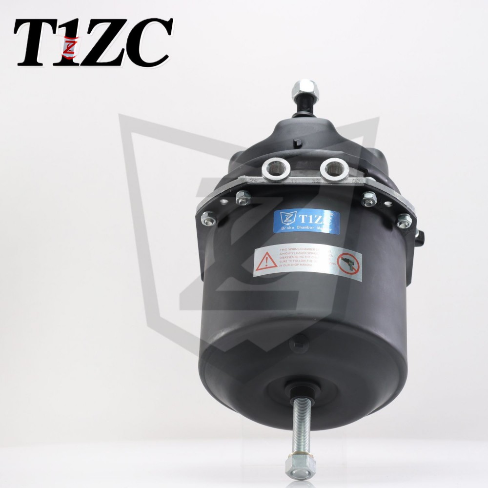
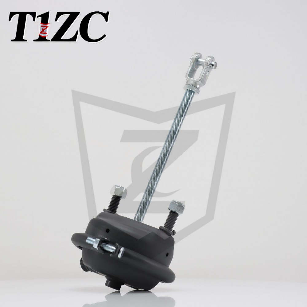 Regular Service Brake Chamber for Heavy-Duty Commercial VehiclesThis brake chamber uses air-pressure piston technology for responsive braking and is built with corrosion-resistant alloy for durability. It suits trucks, buses, and trailers in demanding transport roles.View Product →
Spring brake circuit
In a double-diaphragm (DD) or spring brake chamber, the spring port is pressurized during normal driving. That air holds the power spring compressed and keeps the parking brake released. When the driver sets the parking brake, the air exhausts from the spring port and the spring pushes the pushrod out to apply the brakes. If the supply pressure drops below roughly 414 kPa (60 psi), the spring applies automatically, which is the emergency braking function.
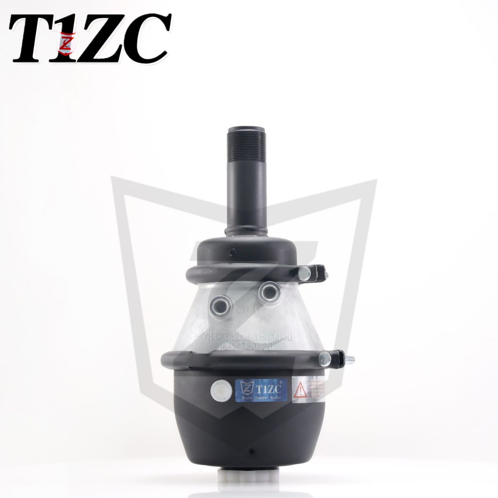
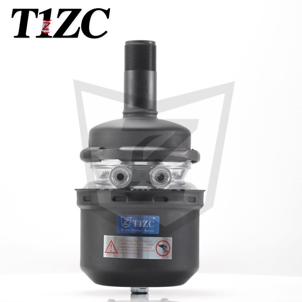
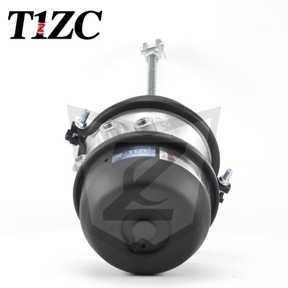 Regular S-Cam Double-Diaphragm Brake ChamberFeaturing dual diaphragms and classic S-cam technology, this chamber provides stable braking force and high durability. It is suited for commercial vehicles under complex working conditions and harsh environments.View Product →
The two-port layout explains why the diagram matters. Connecting the service line to the spring port pressurizes the spring side only, so the parking brake releases but the service brake does not respond. Connecting the spring line to the service port produces the opposite fault: the service brake sees constant pressure while the spring brake cannot hold the vehicle.
Common Faults You Can Trace on a Brake Chamber Air Line Diagram
A diagram becomes a diagnostic tool when you use it to reason backwards from a symptom to a component. Most brake chamber faults show up as a pattern that points directly at a valve, a line, or the chamber itself.
- Brake will not release — check the quick release or relay valve exhaust path, and verify that a constant-supply line was not connected to the service port.
- Slow response on the rear axle — the relay valve may be faulty, or the line from the foot valve to the relay valve is pinched or restricted.
- Parking brake will not hold — look for a leak between the check valve and the spring port; a partially pressurized spring port also causes drag and heat.
- Chamber leaks continuously — listen at the clamp ring, pushrod boot, and line fittings; a damaged diaphragm or loose clamp ring is the usual cause.
- Pushrod returns slowly or not at all — moisture and corrosion inside the chamber can bind the return spring, and blocked exhaust ports trap air behind the diaphragm.
For a step-by-step procedure that covers each test point, our guide to troubleshooting air leaks in an S-cam brake chamber assembly walks you through the checks in the same order as the diagram.
Choosing the Correct Brake Chamber from the Diagram
Brake chamber selection depends on three specifications: the chamber type, the effective diaphragm area, and the available stroke. The vehicle drawing usually stamps these values in the parts list, and replacing a chamber with a different type changes the braking force at the wheel.
| Type | Effective diaphragm area | Theoretical force at 100 psi | Typical position |
|---|---|---|---|
| Type 20 | 20 in² (129 cm²) | 2,000 lbf (8.9 kN) | Steer axle |
| Type 24 | 24 in² (155 cm²) | 2,400 lbf (10.7 kN) | Drive axle or trailer |
| Type 30 | 30 in² (194 cm²) | 3,000 lbf (13.3 kN) | Drive axle or trailer, heavy duty |
Most heavy vehicles use type 24 or type 30 chambers, but the correct choice depends on the axle's brake torque specification. Oversizing causes wheel lock on slippery surfaces, while undersizing increases stopping distance. If the original part number is missing, use the pushrod stroke and the axle's rated load to narrow the selection, then confirm with the diagram or parts list. Type 24 rear chambers are common in single-axle and tandem drive configurations, and a regular-release design fits most standard air line layouts.
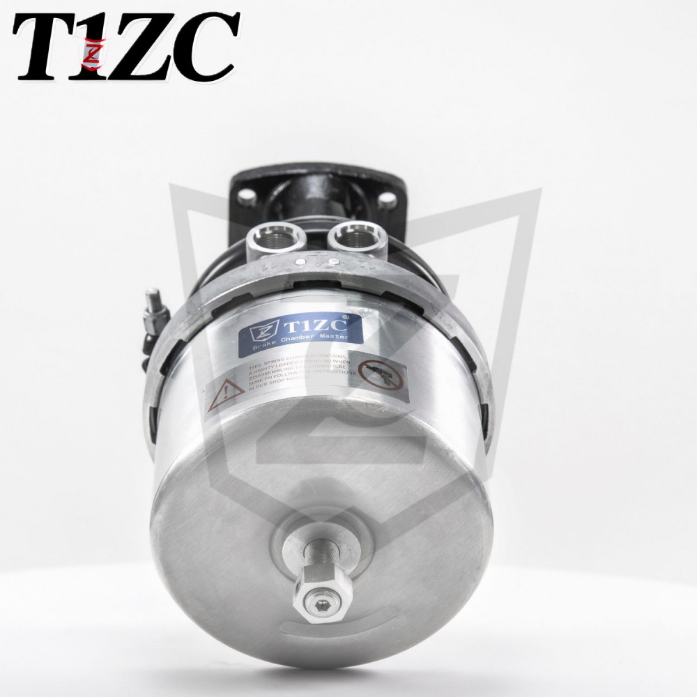
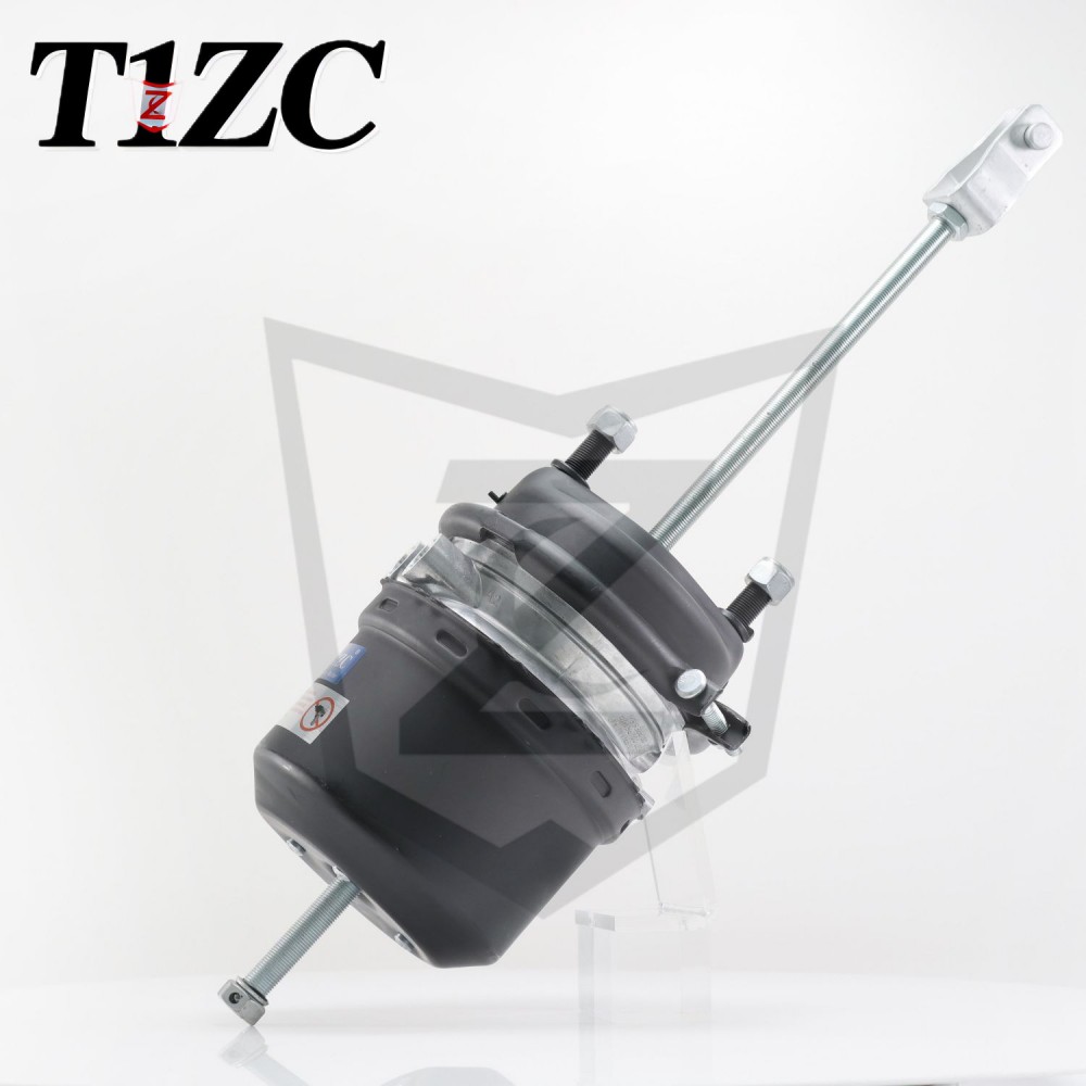 Regular Release T24 Rear Brake Chamber for Heavy TrucksDesigned for high-load tractors and heavy trucks, this T24 chamber handles higher working pressure and extreme temperatures. Its precision pneumatic control and durable materials support reliable braking under heavy loads.View Product →
Frequently Asked Questions
What is the difference between the service port and the spring port on a spring brake chamber?
The service port connects to the foot brake valve and applies the service brake in proportion to pedal travel. The spring port connects to the parking and emergency circuit; it receives air to hold the spring compressed and exhausts air to apply the parking brake.
Why is one line always pressurized while the engine is running?
The supply or emergency line carries constant reservoir pressure to keep the spring brakes released. The service line is pressurized only during a braking event, which is why a supply-line rupture applies the spring brakes automatically.
How can I tell if a diagram uses the red-blue convention or a different one?
Check the legend on the diagram and the gladhand colours at the trailer connection. In North American practice, red is the supply or emergency line and blue is the service line. European and Asian diagrams differ, so trace the line back to the valve function before trusting the colour.
Can I install a type 24 chamber where a type 30 was specified?
No. The effective diaphragm area determines the output force at a given pressure. A smaller chamber produces less force and lengthens the stopping distance, while a larger chamber can generate excess force and cause wheel lock. Always match the type stamped on the original part or listed on the vehicle's brake specification.
A brake chamber air line diagram is more than a reference drawing. It is the fastest way to verify that the air supply, control valves, and chambers are connected correctly, to predict how each circuit behaves under fault conditions, and to choose the right replacement chamber. Keep the vehicle-specific diagram accessible, follow the pressure and stroke specifications, and confirm the port connections before the wheels go back on.