
 EN
EN  English
 Português




Content
- 30/30 Brake Chamber Diagram: Anatomy, Ports, and Maintenance
- What Does "30/30" Mean on a Brake Chamber?
- Anatomy: A Labelled 30/30 Brake Chamber Diagram
- Ports: Which One Applies and Which One Releases?
- How the 30/30 Dual-Diaphragm Chamber Works in Two Phases
- Inspection and Maintenance: What to Check on a 30/30
- Sizing and Replacement: Standard Stroke vs Long Stroke
- Frequently Asked Questions
- Putting the Diagram into Practice
30/30 Brake Chamber Diagram: Anatomy, Ports, and Maintenance
The answer to "30/30 brake chamber diagram" is straightforward: a Type 30/30 is a double-diaphragm spring brake chamber made from two Type 30 chambers stacked together—a service brake chamber on one side and a spring brake chamber on the other. The diagram below and the following sections identify the ports, diaphragms, pushrod, and spring locations, then explain the sequence in which they work.
What Does "30/30" Mean on a Brake Chamber?
The number 30/30 indicates that both halves of the assembly—the service side and the spring side—are Type 30 chambers. Each side has an effective diaphragm area of approximately 30 square inches (roughly 194 cm²), which makes the combined unit a common choice for heavy-duty truck and trailer axles.
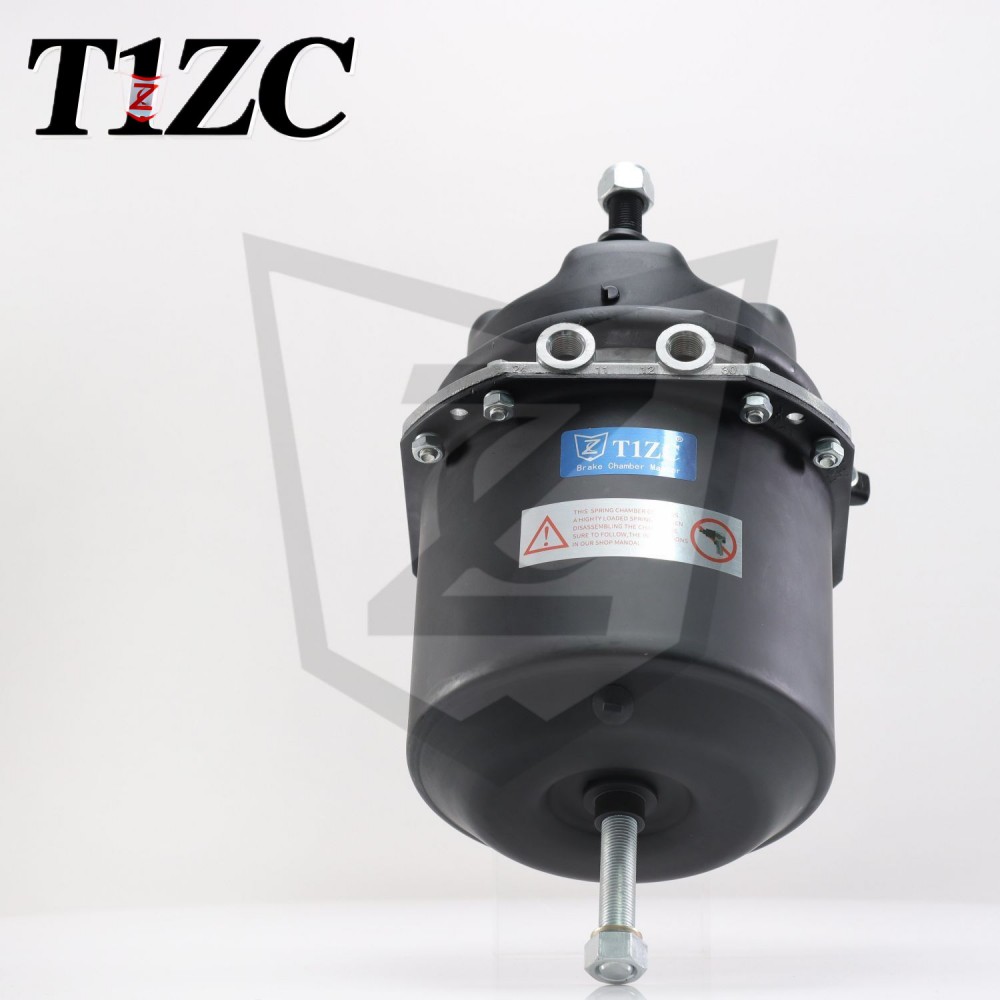
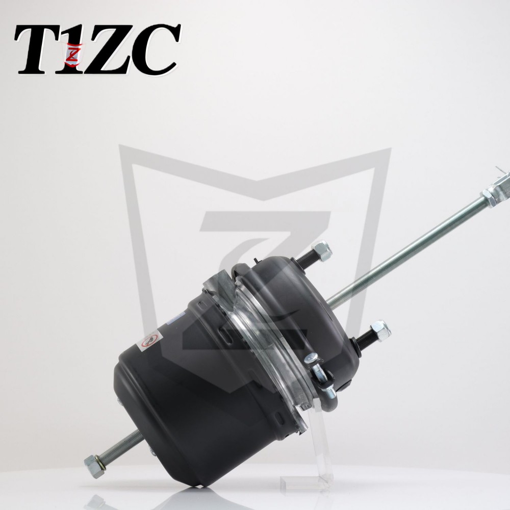
This configuration is sometimes called a "double-diaphragm spring brake." The spring side stores energy in a compressed spring, so when air pressure is released, the spring applies the parking and emergency brake. The service side uses air pressure to apply the normal service brake. A regular release T30 rear chamber in this family is shown below.
Anatomy: A Labelled 30/30 Brake Chamber Diagram
The key parts in any Type 30/30 chamber are the same, but their arrangement matters when you need to trace air lines or replace a damaged unit.
| Part | Location / Description | Function |
|---|---|---|
| Service diaphragm | Mounted on the side facing the pushrod | Converts compressed air pressure into linear force for service braking |
| Spring diaphragm | Located on the rear half of the chamber | Separates the air cavity from the compressed spring and moves with the spring |
| Pushrod | Extends from the service side toward the slack adjuster | Transmits force from the diaphragm to the foundation brake |
| Return spring | Inside the service side | Retracts the pushrod when service air pressure is released |
| Power spring | Inside the spring brake side | Applies parking/emergency braking when air pressure is lost |
| Release port | On the spring brake side | Receives supply air to compress and cage the spring, releasing the parking brake |
The layout is usually symmetrical: a cylindrical housing, a clamp band or bolt ring in the middle, and two ports positioned roughly opposite each other. In many designs the service port is on the rod side, while the spring port is on the rear cover. Some chambers are marked with a cast "S" on the service side and "R" on the release side.
Ports: Which One Applies and Which One Releases?
The port closest to the pushrod supplies the service brake chamber, while the port on the rear cover supplies the spring brake release cavity.
In a standard Type 30/30, when you apply the service brake, air pressure enters the service port and pushes the service diaphragm against the pushrod. When you release the service brake, the pressure decreases and the return spring retracts the pushrod.
For the spring brake (parking brake), the rear port is used to compress the power spring. When the vehicle is parked, the rear port is exhausted, allowing the power spring to push the pushrod and apply the brakes. To release the parking brake, you supply approximately 60–80 psi (about 414–552 kPa) of air to the rear port, compressing the spring and freeing the pushrod.
This is the reason the two ports must never be confused: connecting a service brake line to the spring port can cause unintended parking brake release or failure to release. Trace both air lines back to the dash valves before making any changes.
How the 30/30 Dual-Diaphragm Chamber Works in Two Phases
Service braking is a straight application of air pressure to the service diaphragm; spring braking is a fail-safe mechanism that relies on spring force when air pressure is absent.
During normal driving, the spring brake side is pressurized to compress the power spring. If the air system loses pressure, the spring side exhausts and the power spring pushes the pushrod, applying the brakes. This is why spring brakes are the default emergency brake in commercial vehicles.
In many tandem systems, the two chambers are mounted together but operate independently. The service side works as a conventional brake actuator, while the spring side remains pressurized only when the vehicle is in motion or being repaired with a cage bolt installed.
When performing maintenance, you should always install a mechanical caging bolt before exhausting the spring brake side. Never rely on air alone for service.
Inspection and Maintenance: What to Check on a 30/30
Start by checking the pushrod stroke, then look for air leaks, damaged diaphragm symptoms, and slow response—these four areas cover most 30/30 failures.
- Pushrod stroke: Measure the distance the pushrod moves from its released position to fully applied position. If the stroke exceeds the rated travel, the chamber may be oversized, the slack adjuster is wrong, or the brake shoes are worn.
- Air leaks: Spray soapy water on the ports, clamp band, and threaded connections. Bubbles indicate a leak that can cause slow release or failure to release.
- Response time: Time how fast the pushrod extends when you apply and release the service brake. A sluggish response can mean a restricted air line, a damaged diaphragm, or a weak return spring.
- Physical damage: Look for cracks, rust holes, or bent pushrods at the clamps and base.
For a thorough check of the stroke adjustment process, see our technician’s guide to adjusting brake chamber pushrod stroke, which covers the recommended stroke limits for different vehicle types.
Sizing and Replacement: Standard Stroke vs Long Stroke
The Type 30 size is fixed, but the stroke length varies; choose a chamber with the same stroke rating as the original to avoid overtravel or premature diaphragm wear.
| Specification | Standard Stroke | Long Stroke |
|---|---|---|
| Travel | 2.5 in (64 mm) | 3.0 in (76 mm) |
| Typical axle load | Single trailer axle | Tandem lowbed or heavy trailer |
| Risk of overstroke | Low | Lower |
Typical Type 30 chambers come in standard stroke and long stroke versions. Replacing a long stroke chamber with a standard one reduces the allowable slack adjuster travel and can lead to brake drag, overheating, and uneven tire wear.
Before ordering a 30/30, verify the mounting type, clamp band diameter, port thread size, and whether the chamber is a "regular release" or "quick release" design. Quick release chambers exhaust air faster, which can shorten response times in certain control valves.
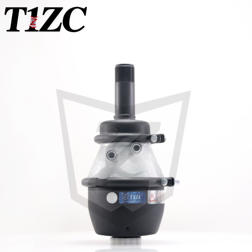
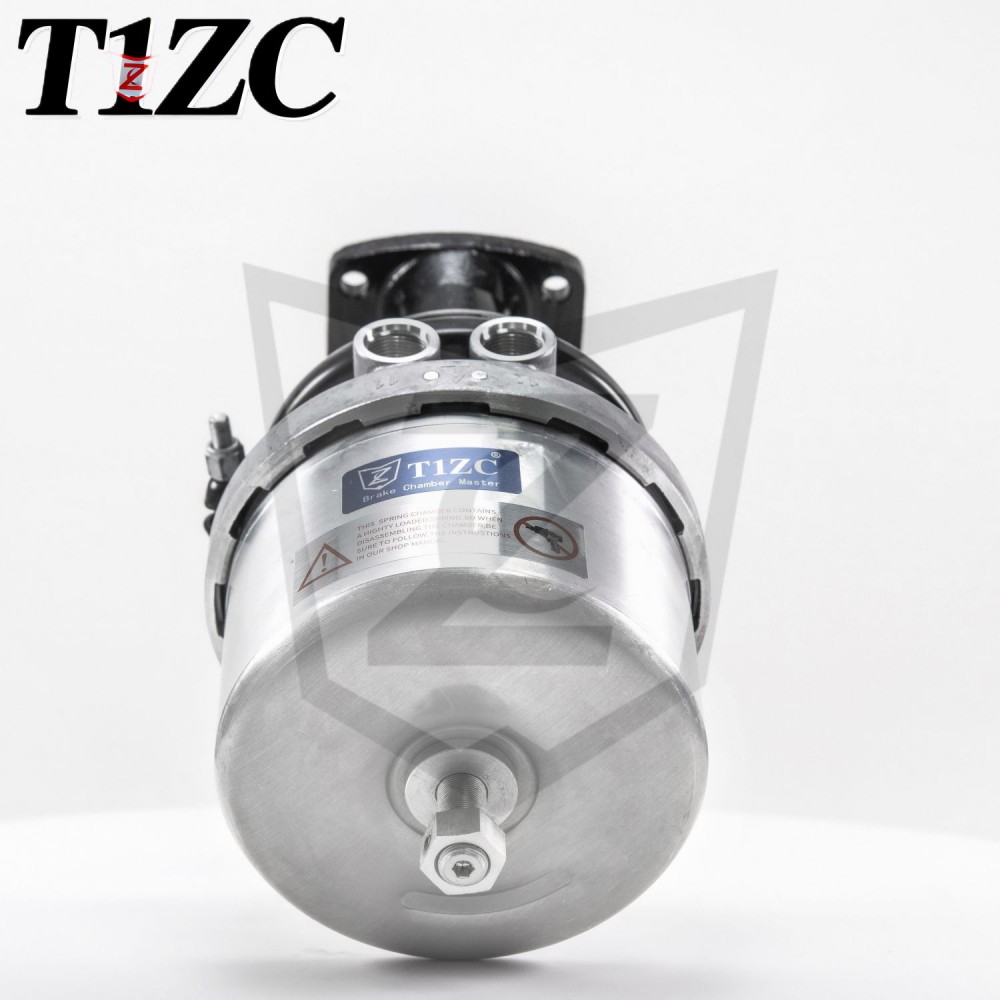
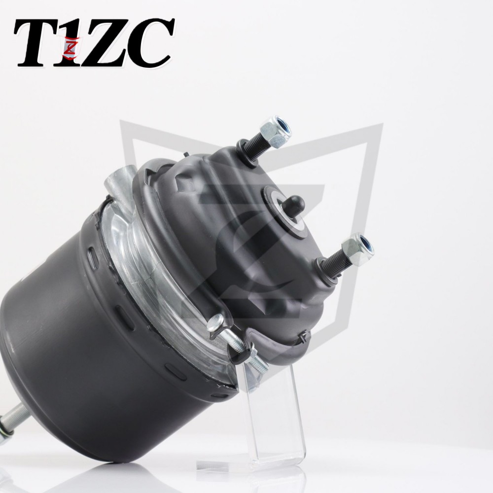
For replacement on a European trailer with a T30 rear chamber, a regular release design matched to the original stroke is the safest choice. A verified product in this category is shown below.
Frequently Asked Questions
What does 30/30 mean on a brake chamber?
It means both the service brake chamber and the spring brake chamber are Type 30, each with roughly 30 square inches of effective area.
Can I replace a 30/30 with a Type 24?
No. A Type 24 has a smaller area and lower output force, which can reduce braking performance. Always match the original size and stroke.
How much air pressure is needed to release the spring brake?
Typically about 414 kPa (60 psi) is required to begin releasing the spring brake, and most systems use full system pressure (about 700–850 kPa) during normal operation.
Why does my 30/30 brake chamber leak air from the spring side?
A leak on the spring side often means the diaphragm is ruptured or the release valve is faulty. Replace the chamber rather than patching it.
What is a caging bolt and when should I use it?
A caging bolt is a mechanical device that holds the power spring compressed. Use it before disassembling the brake chamber or when towing a vehicle with a failed air system.
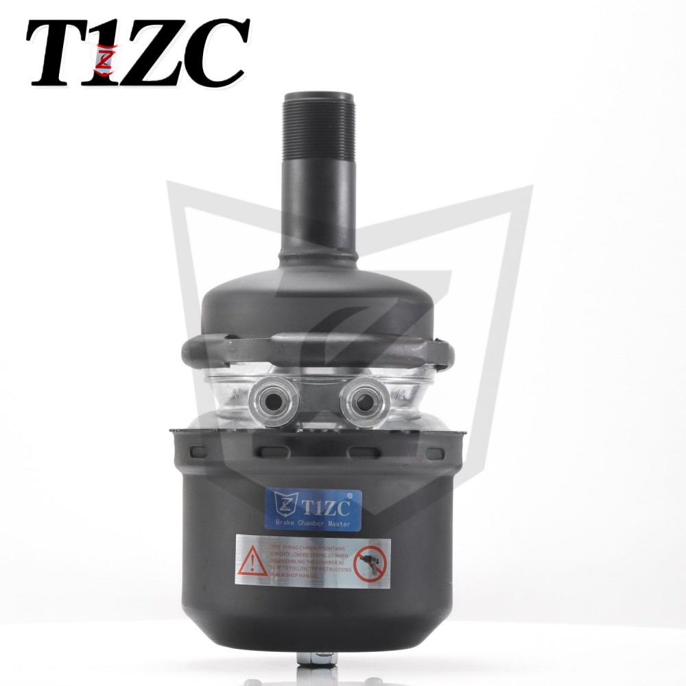
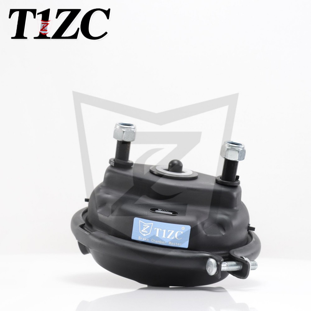
For applications that use a Type 30 single diaphragm chamber on light commercial vehicles, a compatible unit is listed below.
Putting the Diagram into Practice
Once you can read the ports, identify the diaphragms, and understand the stroke requirements, troubleshooting a 30/30 brake chamber becomes a matter of following the air pressure and spring logic. Inspect the pushrod travel first, verify the port routing, and always use the correct replacement size. A well-maintained 30/30 provides reliable service and parking braking for the life of the vehicle.