
 EN
EN  English
 Português




A brake chamber diagram does more than label parts. It shows how a truck or trailer converts compressed air into braking force, whether the unit is a service, spring, or double-diaphragm design, and which components are likely to wear first. Read the diagram correctly, and you can identify the right replacement before you order. This guide explains the main components, compares the common chamber types, and gives practical rules for using the diagram during maintenance and troubleshooting.
Content
- What Is a Brake Chamber?
- Key Components in a Brake Chamber Diagram
- How to Read a Brake Chamber Diagram: Service vs. Spring
- Single vs. Double Diaphragm Brake Chamber Diagrams
- Using the Diagram in Replacement and Maintenance
- Frequently Asked Questions
- What is the main difference between a single and a double diaphragm brake chamber diagram?
- How can I tell from a diagram whether a chamber is a service or spring type?
- Do the type numbers on a brake chamber diagram mean anything?
- Why does my diagram show two air ports on the same chamber?
- Can I use a service brake chamber diagram to order a disc brake chamber?
What Is a Brake Chamber?
A brake chamber is the mechanical converter of an air brake system. It is a round metal housing mounted at each wheel of a truck, tractor, or trailer. When the driver presses the brake pedal, compressed air flows into the chamber, pushes a flexible rubber diaphragm, and forces a pushrod outward. The pushrod rotates the slack adjuster, which turns the camshaft and presses the brake linings against the drum.
From the outside, most chambers look similar, so a diagram is the only practical way to see the internal design. It reveals the diaphragm, return spring, air inlet, and pushrod guide, and it tells you at a glance whether the unit is a service, spring, or double-diaphragm chamber. In shop work, that distinction decides whether the chamber can be replaced with a simpler single-diaphragm unit or must match the existing parking brake system.
Brake chambers come in three families based on the foundation brake they serve: S-cam, disc, and wedge. All three appear in parts catalogues, but the reading principles remain the same.
Key Components in a Brake Chamber Diagram
Although manufacturers draw brake chambers in slightly different styles, the functional layout is consistent. Most service chamber diagrams contain the same set of parts, and the table below lists the ones that matter.
| Component | Function | Visual clue in the diagram |
|---|---|---|
| Diaphragm | Seals the chamber and flexes when air pressure is applied | Curved rubber line stretched between the two housing halves |
| Pushrod | Transfers diaphragm movement to the slack adjuster | Straight rod exiting the housing through a centre guide |
| Return spring | Retracts the pushrod when air pressure is released | Small coil spring drawn inside the rear housing |
| Air inlet port | Connects the service air line to the chamber | Opening on the rear or side of the housing |
| Clamp ring or bolts | Holds the two housing halves and seals the diaphragm | Bolts around the outer edge or a clamp band |
| Mounting studs | Fix the chamber to the axle bracket | Two or four studs on the flat face of the housing |
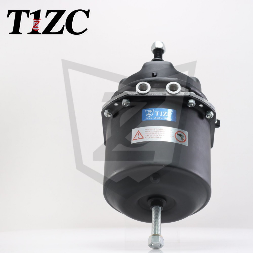
The mounting studs and inlet port are the first details to check when comparing a diagram with a real chamber. They are easy to measure, and they eliminate most wrong fits. On a typical front axle, the standard layout is a single-diaphragm unit like the regular service brake chamber, which follows the classic S-cam arrangement shown here.
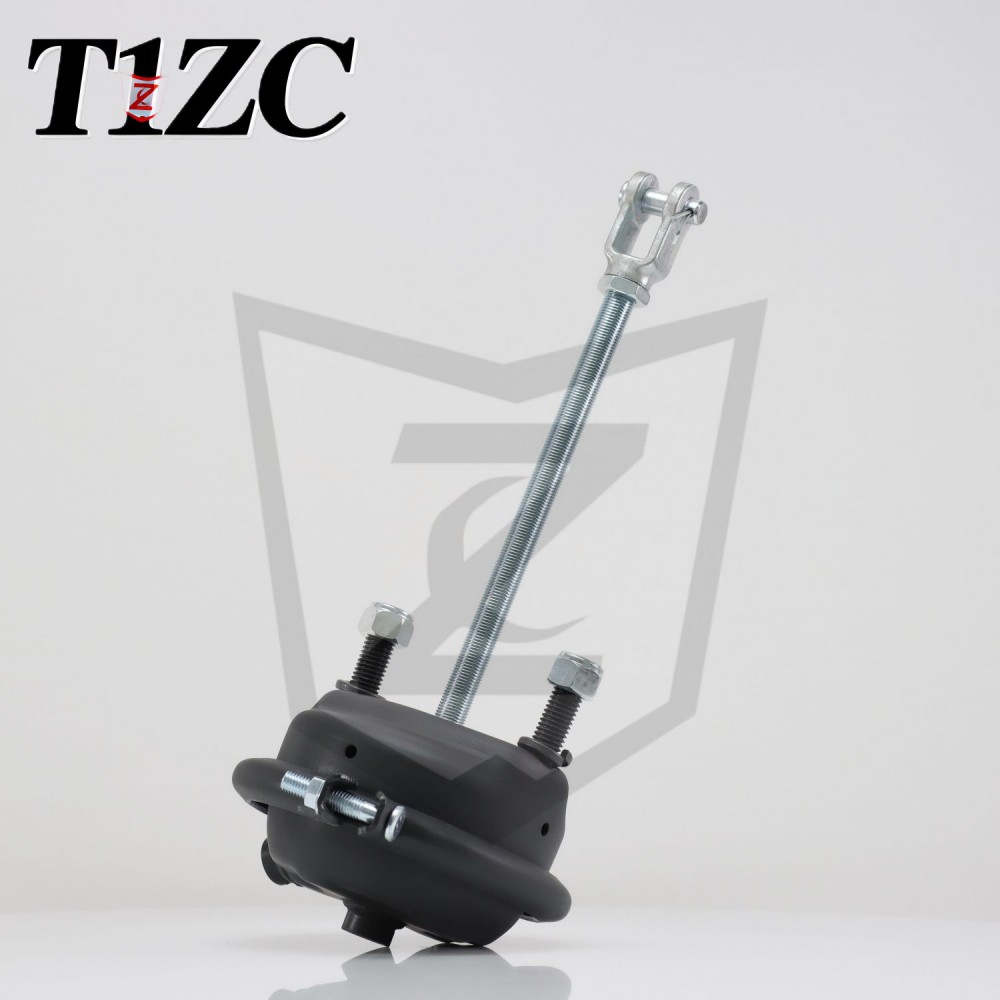 Wholesale Regular Service Brake Chamber Manufacturers, Factory - ZHUJI TEYI IMPOZHUJI TEYI IMPORT&EXPORT CO.,LTD is China wholesale Regular Service Brake Chamber manufacturers and OEM factory,Regular Service Brake Cha...View Product →
How to Read a Brake Chamber Diagram: Service vs. Spring
The first thing to identify in any brake chamber diagram is whether it represents a service chamber or a spring brake chamber. That distinction determines how the spring acts, which ports are present, and how the unit must be handled during repairs.
A service brake chamber uses compressed air to apply the brake and a light return spring to release it. The diagram has one housing, one diaphragm, and one air port. When pressure is exhausted, the return spring pushes the diaphragm back and the pushrod retracts. Service chambers do not provide any parking or emergency braking on their own.
A spring brake chamber combines a service brake with a parking and emergency brake. In the diagram, you will see a second, deeper housing section containing a large power spring. When the vehicle parks, air is exhausted from the rear section and the power spring pushes the service diaphragm forward, applying the brakes. Reapplying air compresses the power spring and releases the brakes. A caging bolt is drawn on the rear cover so a technician can release the spring manually if the air system fails.
| Feature | Service chamber | Spring brake chamber |
|---|---|---|
| Braking functions | Service braking only | Service, emergency, and parking braking |
| Air to apply | Pushes the diaphragm forward | Service port pushes diaphragm; parking port compresses power spring |
| Air to release | Removes pressure, return spring retracts rod | Removes service pressure; service spring retracts rod; parking releases by pressurising rear chamber |
| Diagram clue | Single shallow housing, small coil spring | Two-section housing, large power spring, caging bolt |
| Common location | Front axles, steer axles | Drive axles, trailer axles |
When the diagram shows a power spring, never open the clamp before caging the spring completely. The stored energy in a loaded power spring is strong enough to push the housing cover off with serious force.
Single vs. Double Diaphragm Brake Chamber Diagrams
Spring brake chambers on modern heavy trucks and trailers usually use a double-diaphragm layout. In a DD diagram, two flexible diaphragms are shown: one for service braking and one for the parking/emergency brake. The power spring sits behind the second diaphragm, and both sections act on the same pushrod, so the unit delivers normal braking and a reliable parking function in one package. DD chambers are standard on drive axles and trailer axles.
Single-diaphragm chambers are simpler, lighter, and cheaper. They are used on front steering axles and on vehicles where a separate mechanism handles parking. A single-diaphragm diagram shows one housing, one diaphragm, a small return spring, and one air port. You cannot replace a DD chamber with a single-diaphragm unit if the axle still needs parking.
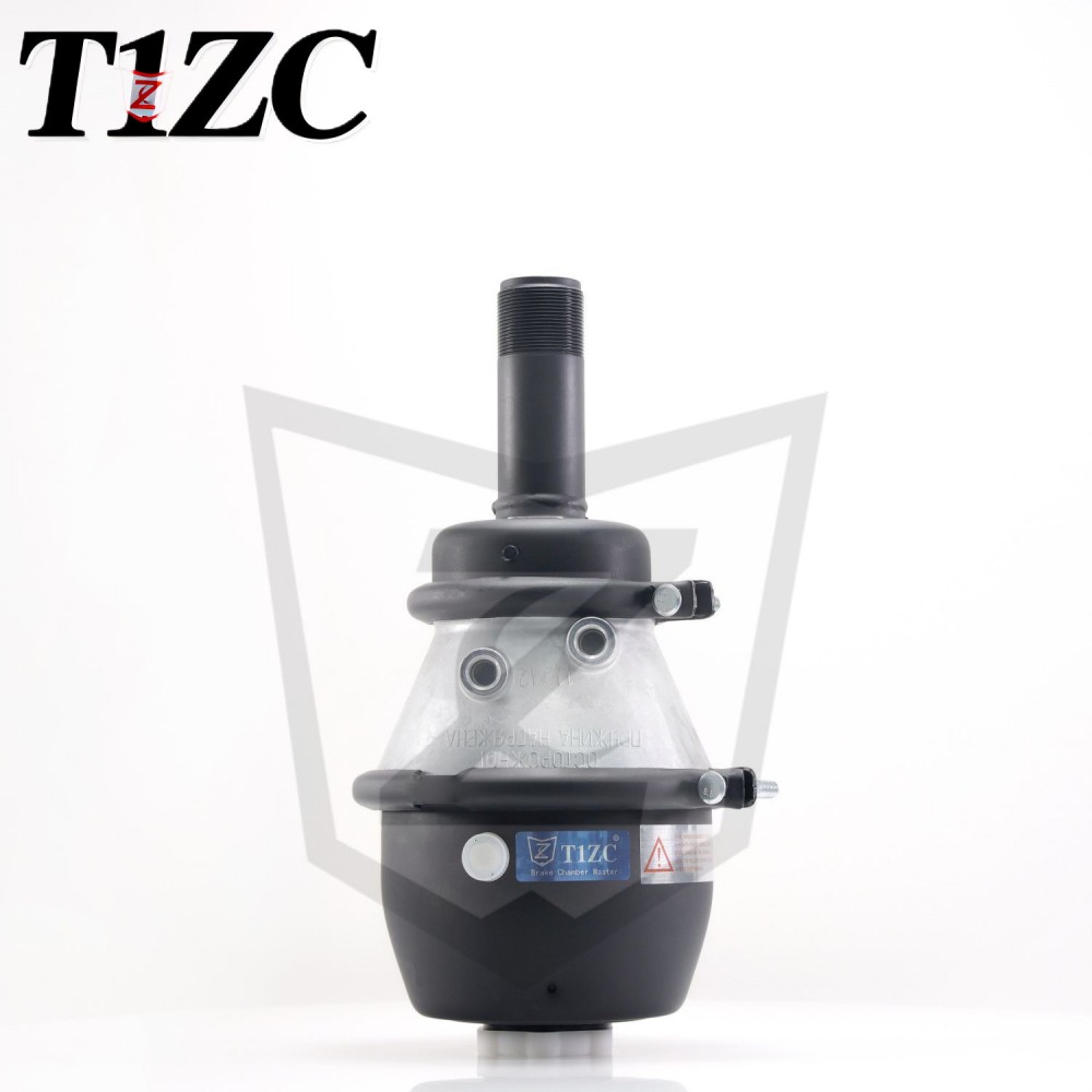
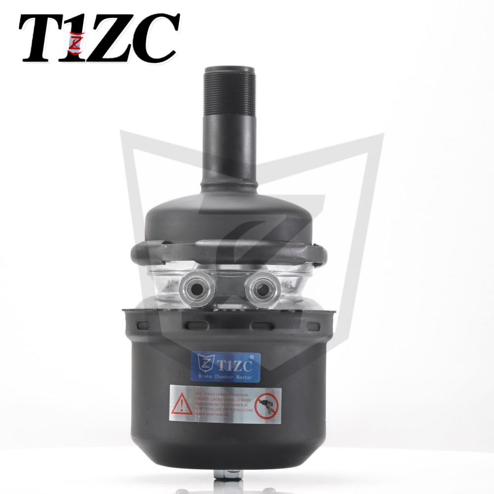
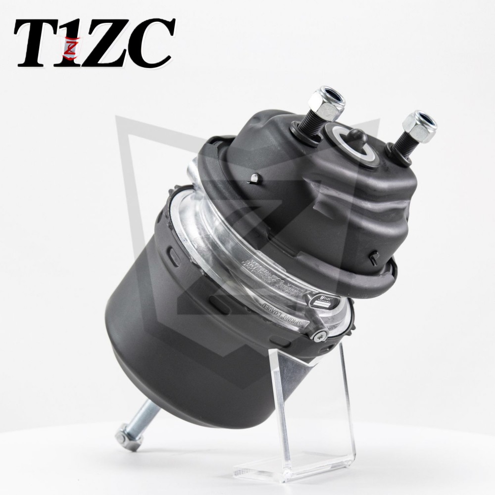
A typical DD product is the regular s-cam DD brake chamber, which follows the double-diaphragm principle in an S-cam drum brake application. Its diagram is a useful reference for identifying the two stacked spring sections on a tractor's drive axle.
 Wholesale Regular S-cam DD Brake Chamber Manufacturers, Factory - ZHUJI TEYI IMPZHUJI TEYI IMPORT&EXPORT CO.,LTD is China wholesale Regular S-cam DD Brake Chamber manufacturers and OEM factory,The Regular S-Cam DD Bra...View Product →
Disc Brake Chamber Diagrams
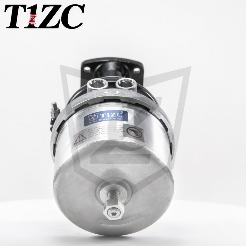
Air disc brakes use the same air-pressure principle, but the chamber diagram looks different. The pushrod acts directly on the caliper rather than through a slack adjuster, so the housing is shallower, the stroke is shorter, and the rod exits on the brake centreline. The type number still corresponds to the diaphragm area. A dedicated product such as the regular release T24 disc brake rear chamber illustrates this compact housing shape and is a good visual match for disc brake diagrams in parts catalogues.
 Wholesale Regular Release T24 Disc Brake Rear Chamber Manufacturers, Factory - ZZHUJI TEYI IMPORT&EXPORT CO.,LTD is China wholesale Regular Release T24 Disc Brake Rear Chamber manufacturers and OEM factory,The Regular...View Product →
Using the Diagram in Replacement and Maintenance
When you compare a brake chamber diagram with the unit you are about to order, four checks prevent most purchasing mistakes.
- Mounting pattern. Count the studs and measure the distance between their centres. A two-hole and a four-hole mounting pattern are not interchangeable.
- Inlet port position and thread size. Note whether the port is on the rear or the side. Service and spring brake ports often use different NPT or metric thread sizes.
- Stroke rating. Check the type number. Type 16, 20, 24, and 30 chambers correspond to different diaphragm areas and typical pushrod strokes; the diagram labels the stroke dimension next to the pushrod.
- Spring configuration. Confirm whether the unit is service-only or combined with a parking spring. A spring chamber must always be handled with its caging bolt fitted.
Stroke length deserves the most attention. If the installed stroke is too short, the brake will not develop enough force; if it is too long, the slack adjuster may travel past its safe range and the brake will drag or fail an inspection. The full adjustment procedure is covered in the technician's guide on how to adjust brake chamber pushrod stroke for different vehicle types. Air leaks, which appear on a diagram as problems around the diaphragm edge or clamp seal, can be traced with a routine leak check before replacing the chamber.
Frequently Asked Questions
What is the main difference between a single and a double diaphragm brake chamber diagram?
A single-diaphragm diagram shows one rubber diaphragm, a small return spring, and one air port; the chamber can apply only the service brake. A double-diaphragm diagram shows an additional large power spring and a second diaphragm or piston, so it also delivers parking and emergency braking. The extra rear housing is the clearest visual clue.
How can I tell from a diagram whether a chamber is a service or spring type?
Look at the rear of the housing. If the diagram shows a large coil spring and a caging bolt, it is a spring brake chamber. If it shows only a small return spring behind the diaphragm, it is a service chamber.
Do the type numbers on a brake chamber diagram mean anything?
Yes. Type 16, 20, 24, and 30 refer to the effective diaphragm area in square inches and are linked to expected pushrod stroke and braking force. Always match the type number, because a chamber with a smaller area will not produce the braking force required for the axle load.
Why does my diagram show two air ports on the same chamber?
Two ports usually identify a spring brake chamber - one for service and one for parking/emergency. Some single-diaphragm chambers are double-piped, but the larger housing and power spring in the drawing make the spring chamber easy to recognise.
Can I use a service brake chamber diagram to order a disc brake chamber?
No. Disc brake chambers have a shorter stroke, a different mounting face, and a lower profile. Use a disc-specific diagram, and check the maximum stroke, mounting bolt circle, and mode of application before ordering.